The situation you have already met
A car comes in. You open the software, pick the ECU, press read and it connects. Or it doesn't. It sits there, retries, times out, and gives you the kind of error message that tells you nothing: "no communication with control unit."
You did not do anything wrong. The ECU is not dead. The cable is fine. What happened is that this vehicle talks on a CAN BUS FD network, and the interface in your hand only understands the older CAN BUS.
This is the most important thing to understand before we explain anything else: CAN BUS FD support is not a performance option you can live without. If the vehicle uses it and your tool does not, there is no slow connection there is no connection at all.
That is exactly why Hexprog II was designed from the beginning around modern vehicles, ECUs and TCUs and why CAN FD was adopted inside the tool itself, rather than treated as an add-on or a future upgrade. The hardware was built for the cars that are actually arriving in workshops today.
First, what a CAN BUS network actually is
CAN was designed by Bosch in the 1980s and standardized as ISO 11898. It was built for one very specific job: let several control units in a car talk to each other over a cheap pair of wires, in an extremely electrically noisy environment, without any single unit being the boss of the network.
Physically it is a differential pair CAN HIGH and CAN LOW running between the control units, with a termination resistor at each end of the line. Differential means the receiving unit does not look at the voltage on one wire; it looks at the difference between the two wires. That is why a CAN BUS survives next to ignition coils, injectors and fan motors that would destroy a normal signal wire.
Many units share the same two wires. Every unit listens all the time. When one wants to talk, it simply puts its message on the bus and if two happen to talk at the same moment, CAN solves it through arbitration. Each message starts with an identifier, and that identifier is also the priority. Transmitting units watch the bus bit by bit while they send, and the moment one sees a bit on the bus that differs from the bit it sent, it shuts up and lets the higher-priority message finish. Nothing is lost, nothing is corrupted, and the most important message in the car always wins immediately. This is why CAN was originally used for engine and emissions control: a signal about ignition cannot wait behind a signal about the radio.
Now the detail that drives our whole story: a classic CAN BUS frame carries a maximum of 8 bytes of data. That number was chosen when the largest thing a control unit had to say was "engine speed is 3400 rpm". It was perfectly adequate then, and it is the reason the industry later had to redesign the format.
On top of raw CAN sits a stack of layers you work with daily without thinking about them. Because a small payload is not enough for a real diagnostic answer, ISO-TP chops large messages into pieces, numbers them, sends them sequentially and reassembles them at the other end. Above that sits UDS, the diagnostic protocol identify the ECU, unlock security access, write the checksum, reset. And above that sit the manufacturer-specific flash protocols and seed-key security. Every byte you write to an ECU passes through all of that.
Why classic CAN BUS hit a wall
Think of a classic CAN frame as a small envelope. Whatever you put inside it 1 byte or 8 you still pay for the envelope, the address, the stamp and the courier trip. Electrically, the fixed part of the frame is roughly eleven times longer than the useful data it carries. Fill half the envelope or a tenth of it, and the cost on the wire barely changes.
So the industry did the obvious thing: to send more data, send more frames. And that is where the pain comes from. Moving any meaningful amount of content means repeating the whole exchange cycle again and again the frame overhead, the ISO-TP handling, the interrupt inside the ECU's microcontroller, the bus turnaround, and the short pause where the receiver decides whether it is ready for the next piece. This per-frame delay is not a minor detail: in a real ECU under real load, that processing latency is often a bigger share of the total time than the bits themselves. More frames do not just mean more bits, it means more work for both sides of the wire, every single time.
Then the file sizes exploded. For many years, re-flashing an engine control unit meant a few megabytes two or three was a big file. Today it is completely normal to face +10 MB and more: calibration data, application software, adaptive values, learning tables, and on many platforms the ECU is only part of what must be updated in one session. Modern vehicle architectures also merged functions that used to live in many small units into fewer, larger domain controllers, so a single control unit now holds far more memory than before.
Multiply a ten-megabyte file by an envelope that holds almost nothing, and you understand why some writes feel endless. And a long session is not only annoying for the customer it is a risk. The longer the tool stays connected and the ECU is in flash mode, the more chances for a weak battery to drop voltage, a door light to wake the bus up, a gateway to interfere, a laptop to sleep, or a USB hub to hiccup. Long transfers are dangerous transfers. Faster is not about saving time, it is about shrinking the window where something can go wrong.
At the same time, cars started carrying ADAS cameras and radar, OTA update capability and far more diagnostic traffic. The bus simply ran out of room.
What CAN BUS FD actually has changed
CAN FD "Flexible Data-rate" was introduced by Bosch and later standardized in ISO 11898-1 for the protocol and ISO 11898-2 for the physical layer. It is not a new network type bolted onto the car. It is the same two wires, the same topology, the same arbitration idea, with the ceiling removed.
The headline features:
The payload grew eightfold up to 64 bytes per frame. That is the heart of the whole thing. The length field became a code table, so a frame can carry 8, 12, 16, 20, 24, 32, 48 or 64 bytes, and the ECU picks the size that fits what it is sending.
Arbitration stayed exactly as it was. The beginning of the frame still runs at the normal bus speed, typically 500 kbit/s, with the same priority mechanism. This was deliberate and clever: the priority rules of the car do not change, and older units on the same bus can still see the start of a frame and back off correctly. Nothing in the vehicle's real-time behavior gets broken.
Then, once the bus is won, the frame raises its own speed. A dedicated flag the bit rate switch bit tells every receiver: "from this point on, listen faster." The data part can run at 2 Mbit/s, and on capable hardware considerably higher. That is where the name Flexible Data-rate comes from: one speed to argue about who talks, a different and higher speed for the actual content.
The frame gained a format flag, so a receiver can tell instantly whether it is looking at a classic frame or an FD frame, and an error state indicator, which lets a failing unit announce its condition instead of just disturbing the bus.
The checksum grew to protect the much longer payload, and the remote request frame type was dropped it did not fit the new format and was not needed.
And the physical layer got its own revision, because driving short bits reliably at several megabits per second on automotive wiring is a different electrical problem than driving slow, long ones. A transceiver built for classic CAN was never designed to switch that quickly and keep the timing symmetrical.
One more point worth understanding: FD does not require the whole car to be converted at once. A vehicle can carry classic CAN networks and FD networks side by side, and a single network can host both kinds of units. What it cannot do is make a classic-only unit understand an FD frame.
Why FD is so much faster and the reason is not the speed number
People usually explain CAN FD as "faster baud rate". That is the weak part of the story, and if you have ever measured a real write you know why.
The real gain is the size of the envelope. With a 64-byte payload, almost the entire frame is data. The fixed frame cost is paid once for a large block of content instead of many times for tiny fragments and, more importantly, the ECU's microcontroller performs one receive-and-process cycle where it previously had to perform many. The overhead that used to dominate the transfer, including the latency inside the ECU itself, collapses.
The higher data rate layered on top is a bonus on top of the bonus helpful, but secondary. Even on a vehicle where the manufacturer does not enable the bit rate switch, the payload gain is fully present and the transfer is still dramatically shorter.
What does that mean in practice? From our own tests and daily workshop observation, a CAN BUS FD write runs at least three times faster than the same operation over classic CAN. We want to be very clear: this is our own measurement and experience, and it is unofficial not taken from any manufacturer specification or third-party reference, and it should not be quoted as an official figure.
It is a floor rather than a promise for honest reasons. On a real ECU the bus is not always the bottleneck: the flash driver, the erase time of the memory, the security access handshake and the checksum routine all take the time they take. The vehicle's chosen nominal and data rates, the block size and flow-control timing of its transfer layer, the load from other units on the bus, cable quality and length all of it shifts the number. What we consistently see is that the bus stops being the limiting factor, and the session stops being long enough to be dangerous.
Why modern ECUs moved to FD
Put the pieces together and the migration becomes obvious.
File sizes went from a couple of megabytes to ten and more, and re-flashing is now routine rather than exceptional not only at the factory, but in the workshop, and over the air. Functions that used to be spread across many small control units are consolidated into fewer, more powerful ones, so each unit carries more memory and more traffic. ADAS and connectivity added data streams that did not exist when 8 bytes seemed generous. A bus whose useful throughput is a few tens of kilobytes per second cannot carry that.
The alternative was Automotive Ethernet genuinely fast, and it is coming, but it needs switches, more expensive transceivers, a heavier software stack and a different wiring design. CAN BUS FD offered manufacturers something very attractive: keep the same cheap two-wire physical network, the same connectors, the same proven robustness and priorities and multiply the payload by eight, with a free speed boost on the data phase. For the control units that need real bandwidth but not network-grade bandwidth, it is simply the better engineering compromise. That is why it landed in powertrain, transmission and domain controllers exactly the ECUs and TCUs we work on before anywhere else.
Why this has to be supported in the tool's hardware
Now the part that decides whether you connect or not.
A classic CAN controller cannot decode a CAN FD frame. This is not a question of speed or of a missing driver. The frame format itself is different different fields, different length coding, a different checksum, a mid-frame change of bit rate. A controller designed for the classic format has no way to interpret it, and no firmware update can add logic that does not exist in silicon. From the user's side the symptom is exactly the one we started with: the tool sends, nothing useful comes back, the session times out, and the vehicle looks unsupported when the real problem is the interface.
And there is no user setting that fixes it. You cannot choose whether to use FD. The ECU decides. If the network and the target unit use FD frames, that is what comes back on the wire, and a tool that cannot speak it is outside the conversation. A professional tool must detect the format on its own and adapt the tuner should never have to guess, and should never be punished for guessing wrong.
The transceiver matters just as much as the controller. FD's shorter bits need a transceiver designed and specified for FD that is precisely what ISO 11898-2 FD means. A classic transceiver may appear to work at conservative rates and then produce bit errors, corrupted frames and retries at real data rates, and retries during a flash session are the last thing you want. Note also that on some FD vehicles the OBD connector brings out a second twisted pair used for the FD data phase, in addition to the classic CAN pair so the physical signal path of the interface is part of the story, not just the software.
Finally, FD requires the interface to run two separate bit-timing domains and switch between them in the middle of a frame, with correct sample points on both sides. That is a job for dedicated hardware working in real time. Anything that bridges, converts or emulates the format adds delay and jitter and adds a failure point in the middle of a write, which is exactly where a failure costs you a damaged ECU.
How Hexprog II handles CAN BUS FD
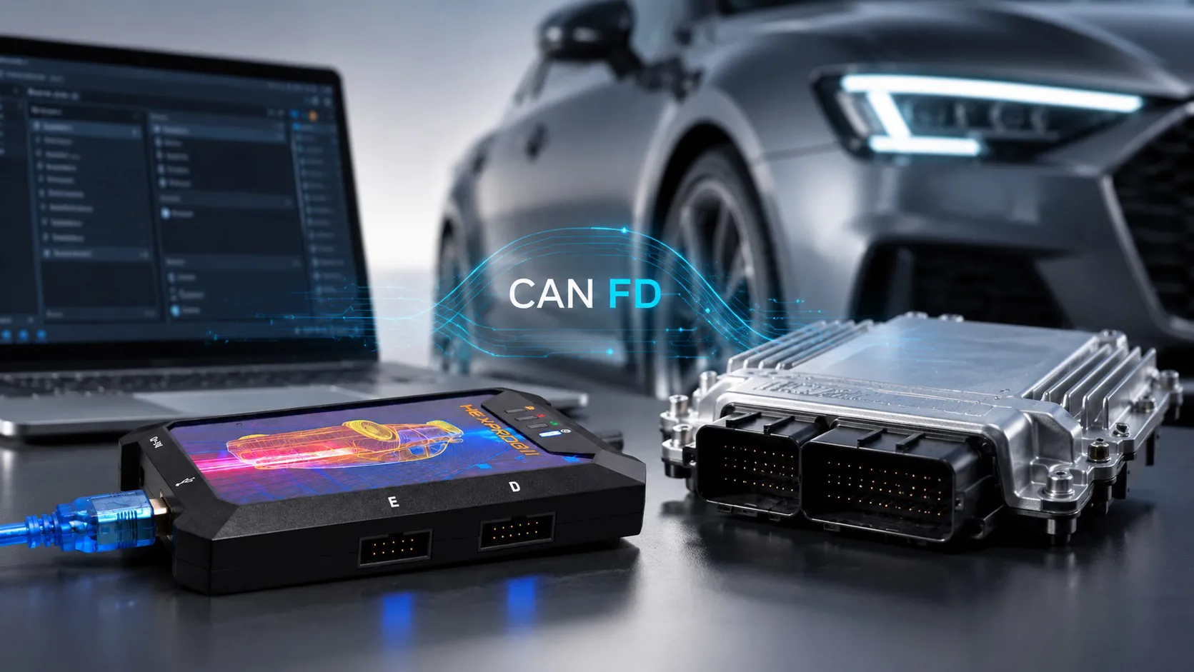
Hexprog II supports CAN BUS FD natively and internally, on both of its CAN channels. The FD handling lives inside the tool, in the signal path itself: frame format detection, the mid-frame bit rate switch and both timing domains are managed at hardware level, with a transceiver specified to ISO 11898-2 FD and data-phase support at full speed, up to 5 Mbit/s. There is nothing to enable in the software the tool works out what the vehicle is using and adapts.
This is a design decision, not a revision. Hexprog II was conceived for current and upcoming vehicles, which meant accepting that FD would stop being an exception and become a requirement so it was built into both channels from the start rather than added to one of them later.
And the two channels are not decorative. Hexprog II uses CAN BUS channel 1 for OBD work, and uses both channels together for Bench and Boot modes. That distinction is exactly why FD had to be present on both:
- Over OBD, the vehicle decides the format. On an FD-equipped car, channel 1 must be FD-capable or the session never starts.
- On the bench or in boot mode, the target ECU decides. An ECU whose flash and diagnostic interface is implemented on an FD network will answer with FD frames even when it is sitting on your workbench with the connector cut open a classic-only second channel will not read it, not on a bench, not in boot, not at any speed. If the ECU supports FD, the channel talking to it must support FD as well.
That is the practical consequence we want every user to take away: FD support on a single OBD channel is not enough for real workshop work, because the majority of the jobs we do tuning, cloning and repair of ECUs and TCUs move between the diagnostic connector and the bench, and both paths have to be ready for the newer format.
Because the FD logic is inside the tool rather than assembled around it, both channels behave consistently: the same timing quality, the same automatic handling, the same reliability whether you are reading through the diagnostic socket or working directly on the ECU's network lines. For cloning especially, where large blocks of data move between two units, the 64-byte frame is where the benefit shows up most clearly.
The scope is exactly what you do every day: tuning, cloning and repair of ECUs and TCUs. On FD-equipped vehicles and units, operations that would be painfully long or simply impossible on a classic-only interface complete in a fraction of the time, with a much shorter window for anything to interrupt the write.
A few habits still matter, and FD does not change them: use a stable power supply rather than a weak battery; keep cables short and in good condition, avoid long unshielded extensions; never interrupt a write; keep the ignition state as the procedure requires; and keep firmware and software current, since vehicle and ECU coverage is extended continuously.
Short answers
Do I have to select CAN FD in Hexprog II? No. There is nothing to choose. The tool detects what the vehicle or the ECU uses and adapts.
Why do both CAN channels need FD? Because Hexprog II works on OBD with channel 1 and on Bench/Boot with both channels. An FD-capable ECU on the bench still speaks FD, so a classic-only channel cannot work on it.
If my car is not FD, do I lose anything? No. FD support is backward compatible on the tool side; classic CAN networks and classic ECUs are handled exactly as before.
Is FD always three times faster? That number is our own observation from tests and workshop use, and it is unofficial the actual result depends on the vehicle, its configured rates and the ECU's own flash and security timings. In every case the session is shorter and more robust.
Does FD mean every car or ECU is supported? No. FD capability is a hardware requirement, but coverage is still per-protocol and per-manufacturer. Always check the coverage list before a job.
Can FD be added later with a firmware update? No that is the whole point of this article. FD needs a capable controller and a transceiver specified for FD. It has to be in the hardware from the start, which is why it is built into both CAN channels of Hexprog II.
Bottom line
Classic CAN BUS was designed when a tiny payload was plenty and a 3 MB file was huge. Modern ECUs and TCUs carry ten times that, and the network had to grow. CAN BUS FD grew it the sensible way same wires, same robustness, same priorities, eight times the payload, a faster data phase, and a physical layer specified to handle it.
For a tuning tool this is not a line on a spec sheet. It is the difference between connecting and not connecting, on the diagnostic socket and on the bench. Hexprog II was designed for modern vehicles, and carries CAN FD internally on both CAN channels, with an ISO 11898-2 FD transceiver and data-phase support up to 5 Mbit/s so FD vehicles and FD ECUs are just another job, not a wasted trip.